How to Create Printable 3D Models for 3D Printing (Step-by-Step Guide)
A complete guide to creating printable 3D models for 3D printing. Learn exact design rules, wall thickness, tolerances, Meshmixer repair, file formats, and AI workflow to stop failed prints.
You spent six hours designing the perfect part. The walls look right. The dimensions check out. You hit export, load it into your slicer, and start the print. Twenty minutes later, the first layer doesn't stick. An hour in, the walls start to sag. Two hours in, it's a tangled mess of filament on your build plate.
The printer isn't the problem. It's the gap between what looks right on screen and what can actually be printed. This guide covers wall thickness, overhang angles, tolerances, mesh integrity, drain holes, and minimum feature sizes. Let's dive in!
Why Most 3D Models Fail When Printed
A 3D model can look completely correct on your screen, and still fail when printed.
This is one of the most common and frustrating problems in 3D printing. Everything seems fine inside Blender, Fusion 360, or any CAD software. The model renders properly, the shape looks solid, and nothing appears broken.
But once you export it to a slicer, everything changes.
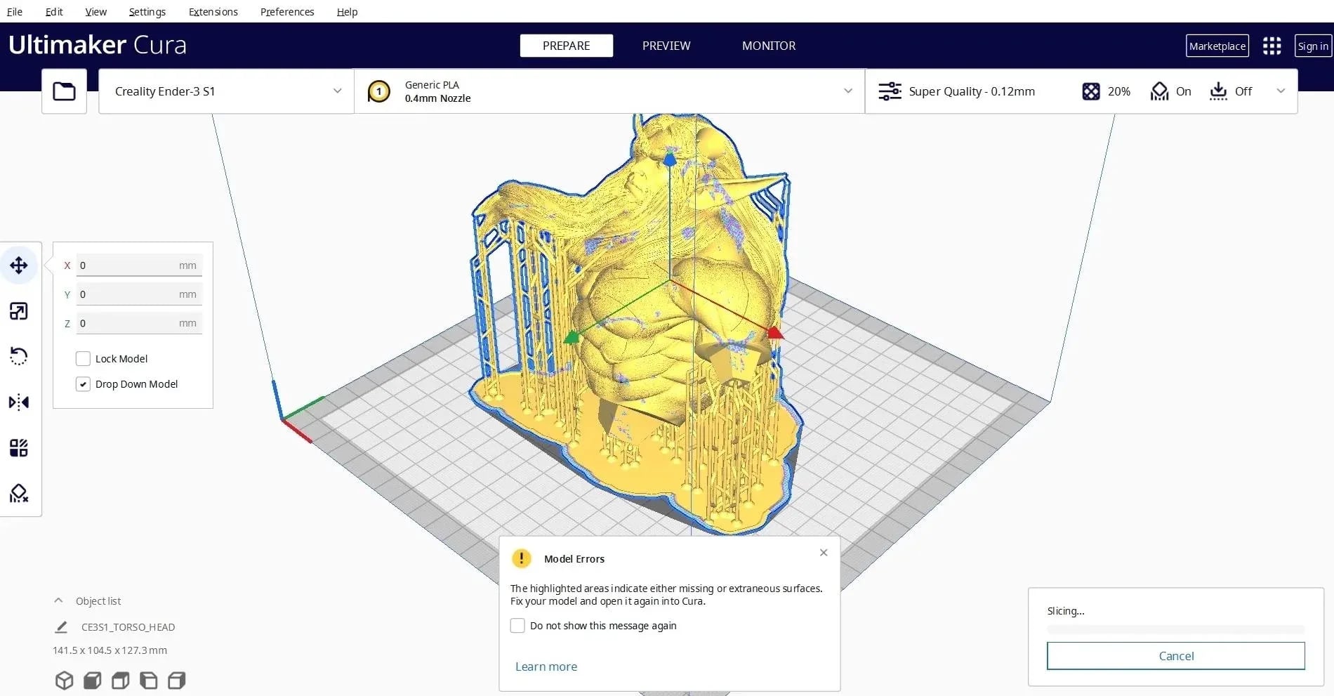
Suddenly, you see errors like:
- missing faces or holes in the mesh
- thin walls that collapse during slicing
- inverted normals or broken surfaces
- prints that fail halfway through
At that point, most beginners assume the printer is the problem.
It usually isn't.
The real issue is that a 3D printable model is not defined by appearance, but by whether it behaves as a physically valid object after slicing.
What Makes a 3D Model Actually Printable
Before modeling, you need to understand one core principle:
3D printing is physical, not visual.
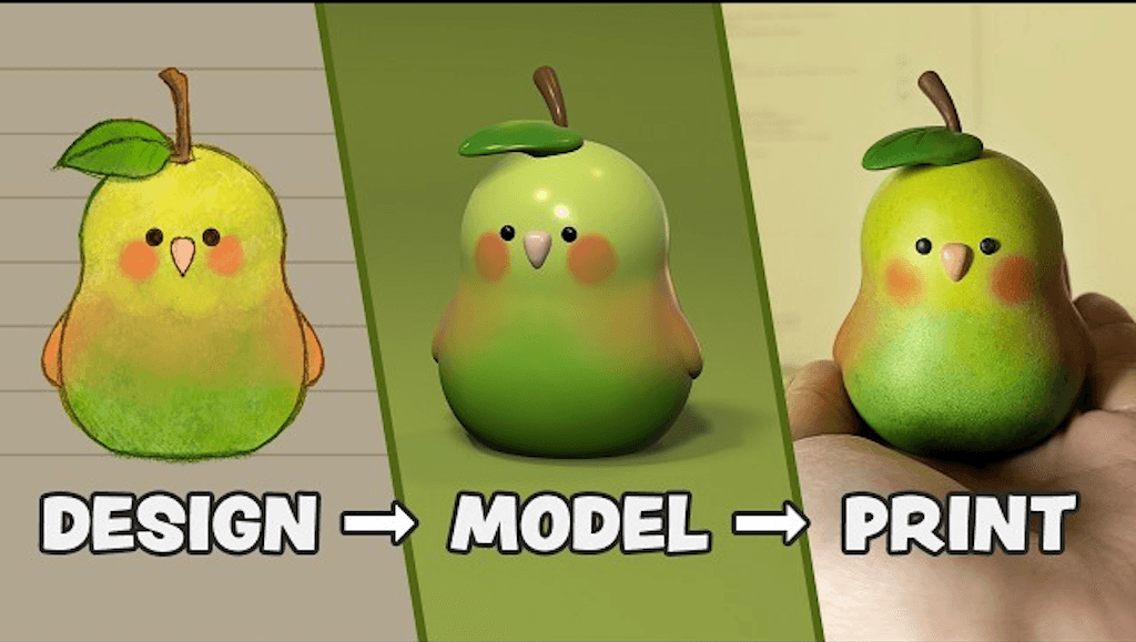
A printable model must meet these conditions:
- Watertight (no holes in the mesh)
- Manifold (clear inside vs outside geometry)
- Non-self-intersecting surfaces
- Structurally thick enough for printing
- Proper real-world scale
If any of these fail, the model can break during slicing or printing-even if it looks perfect in the viewport.
Two Ways to Create 3D Models Today
There are currently two practical workflows for building 3D printable models.
Traditional Workflow: Manual Modeling
This is the standard approach used in tools like Blender, Fusion 360, and SolidWorks.
It involves:
- Constructing geometry manually
- Managing topology and structure
- Fixing mesh errors repeatedly
- Iterating through trial and error
This method offers full control, but the bottleneck is not creativity-it is technical setup and cleanup.
Beginners often spend more time fixing geometry than actually designing.
If you're selecting tools for this stage, see The Best CAD Software for 3D Printing in 2026 for a full breakdown of options.
Modern Workflow: AI-Assisted Generation
A major shift in 3D modeling is not better tools-it is faster access to usable geometry.
In traditional workflows, every idea starts from zero. You block out shapes, fix early mesh issues, and only then reach something usable for refinement. The process is slow, repetitive, and often discourages iteration.
AI tools change this starting point.
Instead of building geometry manually, tools like Triverse AI generate structured 3D base models directly from text prompts or reference images. This removes the most time-consuming part of the workflow: the initial construction phase.
The impact becomes clearer in practice:
- faster transition from idea to print-ready base model
- Fewer early structural errors in the mesh
- More time spent on design decisions instead of setup
This does not mean the model is finished or production-ready. It means you are no longer starting from nothing.
The difference becomes even clearer when comparing Image to 3D vs Text to 3D workflows. Both generate base geometry, but they interpret input differently-visual reference vs language-driven generation-resulting in different starting structures.
Step-by-Step Workflow for 3D Printing
Once you understand the structure and tools, the actual workflow becomes straightforward.
Step 1: Define Your Idea
Before opening any software, sketch on paper:
- Basic shape
- Approximate dimensions
- Intended use (decorative or functional)
- Print orientation
A quick sketch prevents major redesigns later.
Your printer type also affects the detail and support requirements. If you're still choosing a process, compare FDM and resin printing before building the model.
Step 2: Generate a Base Model
AI tools such as Triverse AI can create a rough 3D model from text or images in seconds. The value here is not final quality-it is speed of iteration.
This is especially useful when:
- Testing ideas quickly
- Avoiding early CAD setup overhead
- Creating multiple variations of a concept
Think of this step as skipping the "blank canvas problem".
Step 3: Refine in Blender or CAD Tools
Once you have a base model, refinement happens in traditional tools like Blender or Fusion 360.
This is where real design work begins:
- Adjusting proportions
- Cleaning surface geometry
- Adding functional details like joints or holes
- Improving smoothness and structure
At this stage, you are editing something usable, not building from zero.
Step 4: Validate Printability
This is the most important step many people skip.
- Open the model in Autodesk Meshmixer → Edit → Make Solid → Accept defaults (fixes ~80% of issues).
- Check for non-manifold edges, flipped normals, thin walls, and holes.
- For stubborn problems, use Autodesk NetFabb (click the red X).
The 5 rules below are the most common causes of failed prints. Follow them before exporting.
Rule 1: Wall Thickness
The #1 cause of failed prints.
Material | FDM Minimum | SLA/Resin Minimum | Functional Parts |
|---|---|---|---|
PLA | 1.5mm | 0.5mm | 2.0-3.0mm |
PETG | 1.5mm | 0.6mm | 2.0-3.0mm |
ABS | 1.8mm | - | - |
TPU (Flexible) | 2.0mm | - | - |
For more detail on how printer type, nozzle size, material, and use affect this choice, see our 3D printing wall thickness guide.
Rule 2: 45-Degree Overhang Rule
Surfaces steeper than 45° need supports. Use 45° chamfers to make features self-supporting. Place support contact points on hidden surfaces.
Tree supports are one option for supporting overhangs. Our tree support guide explains when to use them and how to adjust the settings.
Rule 3: Tolerances for Moving Parts
- Snap-fit joints: 0.2-0.3mm clearance per side
- Hinge pins: 0.2-0.3mm clearance
- Press-fit: 0.1-0.2mm interference. Always print a small test piece and measure with calipers first.
Rule 4: Drain Holes for Hollow Prints
Add at least two holes (one at the lowest point). SLA: 4-6mm diameter; FDM: 3mm is enough.
Rule 5: Minimum Feature Size
- Raised text: 1.5mm tall × 0.8mm thick
- Engraved text: 1.0mm tall
- Pillars/pins: ≥2.0mm diameter
- Thin ribs: ≥1.5mm thick
Step 5: Export and Slice
Recommended Formats:
- STL: Universal compatibility (export in binary mode).
- 3MF: Modern slicers - preserves color, material, and settings.
- OBJ: Good intermediate format from Blender.
Compare STL, OBJ, and 3MF if you need a closer look at model data, color support, and slicer compatibility.
In your slicer (Ultimaker Cura, PrusaSlicer, etc.):
- Optimize orientation for bed adhesion and minimal supports.
- Check the first 10 layers carefully.
- Run a 20mm calibration cube first for new materials.
For a fuller explanation of layer height, walls, supports, and other options, see our 3D printing settings guide.
Guides for Your Printing Project
Continue with a guide that matches the object you want to make:
- 3D printing miniatures — Compare model sources, creation tools, and preparation for small figures.
- D&D miniatures — Follow a tabletop character workflow covering prompts, sizing, and resin print preparation.
- Food models for 3D printing — Create miniature props or life-size display replicas, with food-specific shape and finishing choices.
Common Reasons 3D Prints Fail
- Geometry Integrity Issues - Non-manifold geometry, holes, flipped normals, self-intersecting meshes.
- Structural Design Limitations - Walls too thin, unsupported overhangs, weak internal structure.
- Slicing Configuration Errors - Wrong scale, bad supports, incorrect temperatures/speeds.
- Early Design Mistakes - Designing for visuals instead of print physics.
Printability Checklist (Before Slicing)
- Is Mesh watertight and manifold?
- Do all walls meet minimum thickness?
- Overhangs ≤45° or properly supported?
- Hollow parts have drain holes?
- Model repaired in Meshmixer?
- Slicer preview (especially first layers) looks good?
Why Triverse AI 3D Generation Changes the Workflow
Traditional modeling requires full manual construction before a usable model exists. AI-assisted workflows like Triverse AI remove this constraint.
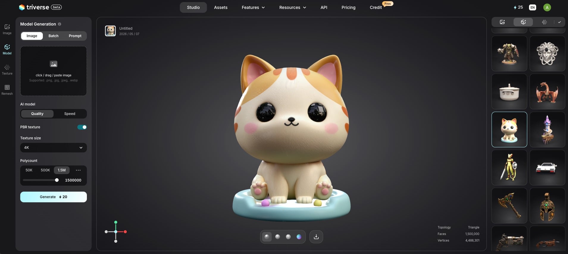
Old way: Idea → Manual modeling → Debugging
New way: Idea → AI base → Refinement → Print
The key shift is not automation-it is reduced time to reach usable geometry.
Less time is spent building the structure. More time is spent making design decisions.
Conclusion
Creating printable 3D models is not about fancy software; it's about understanding print physics and following a solid workflow.
Combine AI for speed, CAD for precision, apply the 5 key design rules, and always validate in Meshmixer. Do this consistently, and your print success rate will improve dramatically.
The gap between a model that looks good and one that actually prints well is now smaller than ever.
Start today - turn your ideas into real prints.
FAQs about Making 3D Models for 3D Printing

Dennis Kirk is an AI 3D specialist and game developer with more than 5 years of industry experience, mastering production workflows across Unity, Unreal Engine, and Godot. He focuses on demystifying next-generation 3D workflows for creators of all skill levels. His writing spans hands-on technical walkthroughs, asset optimization strategies, and in-depth software reviews, helping developers build faster and smarter.